No Weld Bowpress
This is not an Item I sell. I'm posting it here for do it your self folks to get the instructions on how to build it.
here it is on archery talk too: https://www.archerytalk.com/vb/showthread.php?t=2167188
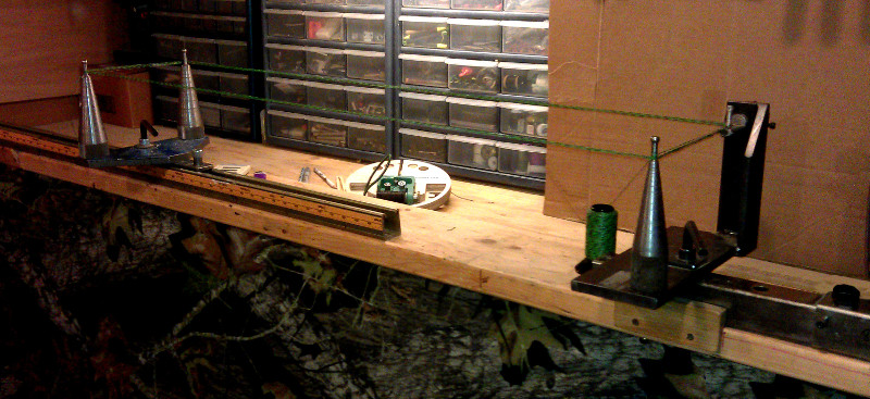
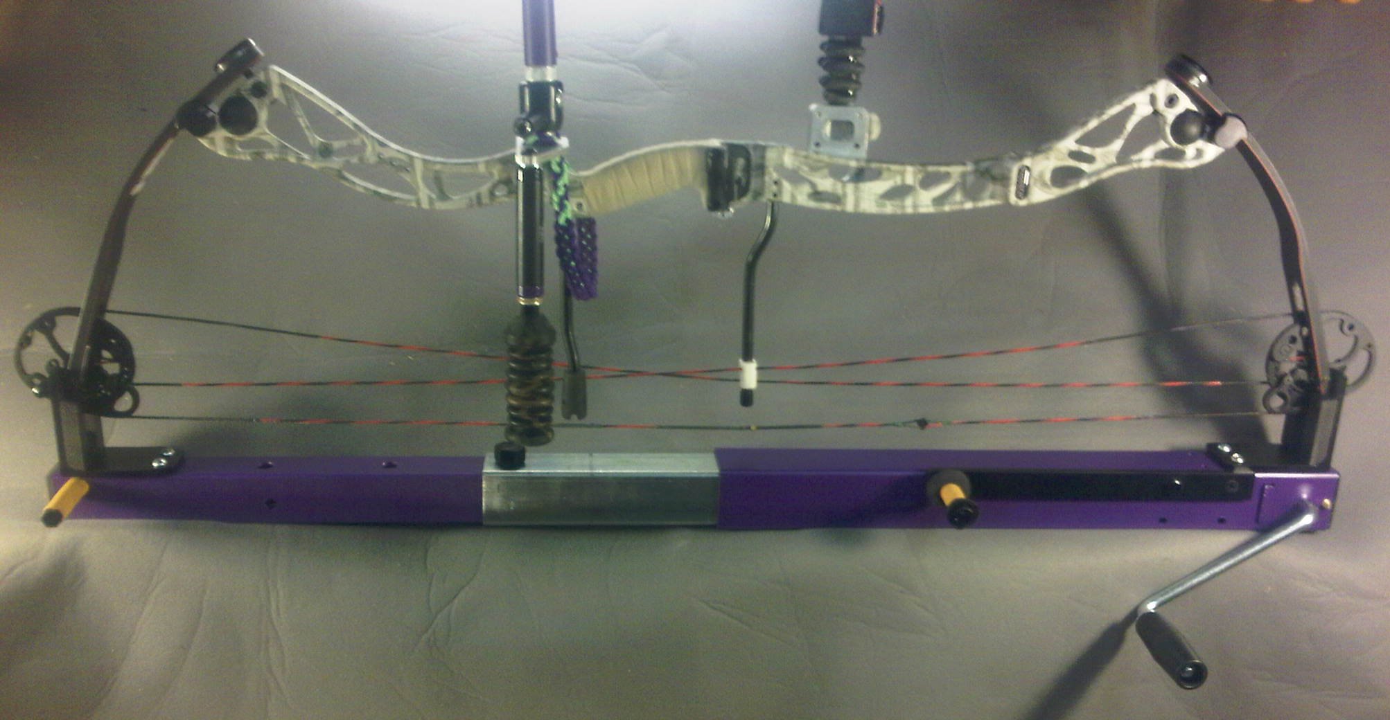
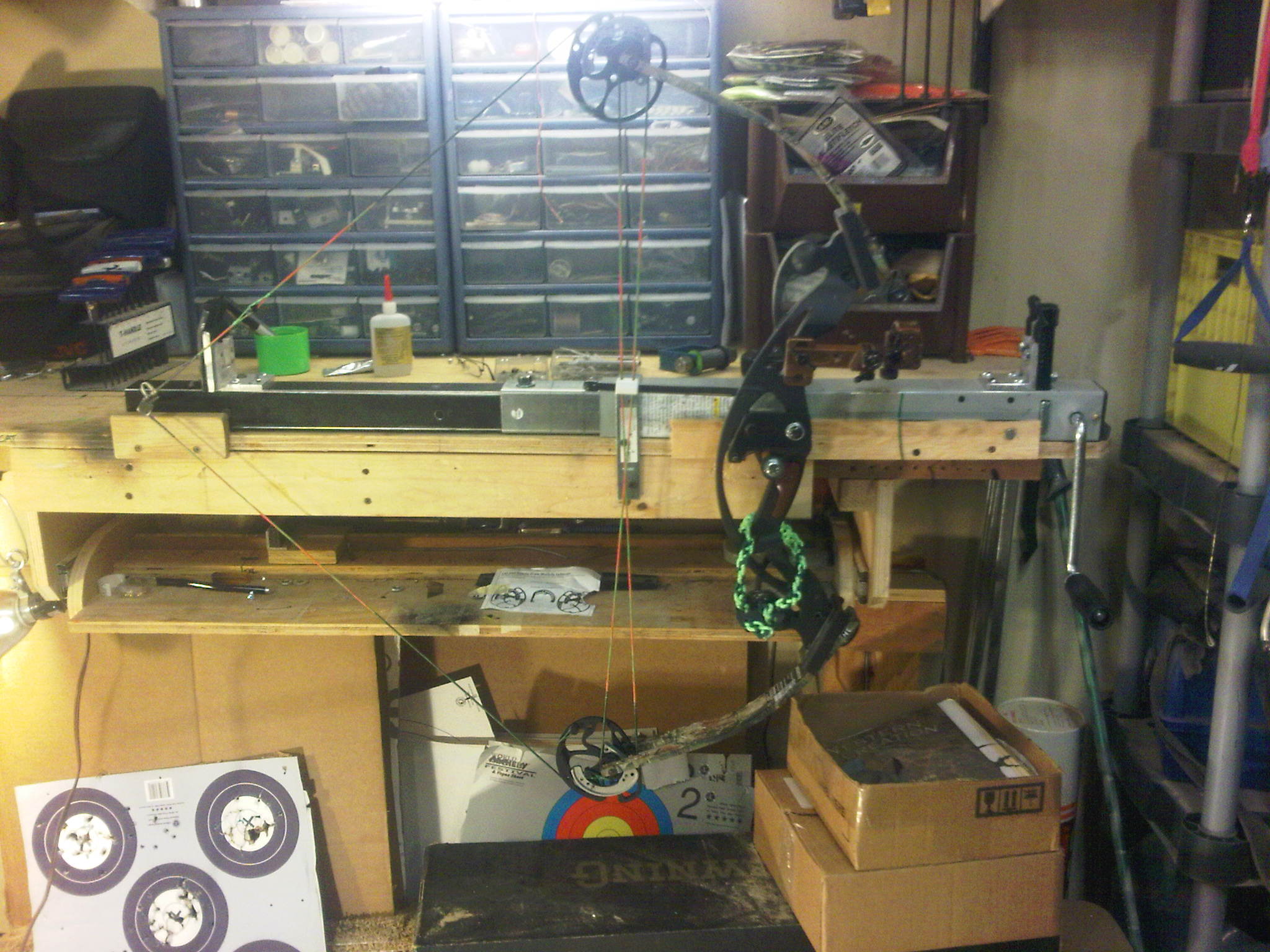
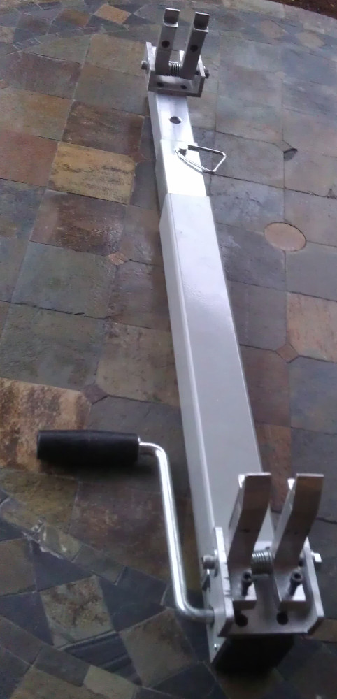
Not having a welder is a serious liability when trying to build a bow press. After looking at the pipe clamp press on the archery talk forums I decided a better solution would be to mount the same sort of fingers on a trailer jack. This gave me the benefit of having enough travel to completely disassemble a bow and yet it was inexpensive and relatively easy to build. Best of all it required no welding. I did a lot of experimenting with steel fingers using grinder cutting wheels and a bench grinder but what I finally settled on was this design that is made completely out of Aluminum. I prefer aluminum to steel because it can generally be milled using the same power tools you would use for in a wood shop. The finger design was completely cut out using my chop saw a hack saw and a drill press.

Here is a list of tools and materials you’ll need:
> Chop saw or table saw.
> Drill press
> Hacksaw
> Belt sander (Optional if you want smother finishes.)
9/16 drill bit
1/4 drill bit
#9 drill bit - for holes that the 10-24 bolts fit through
#7 drill bit - for holes to be threaded with 10-24 taps usually come with the correct drill bit.
#25 drill bit - for holes to be threaded with 1/4-20
F – drill bit - for holes to be threaded with 5/16-18
5/16 drill bit
5/8” drill bit - for counter sinking the screw holes
3/4 drill bit - with a 1/2” shank so it fits your drill press chuck.
5/16-18 Tap and Die
1/4–20 Tap
10-24 tap
And here are the materials you will need:
4 – 5/15-20 x 3.5” bolts Socket head
8 – 1/4-20 x 1/2” bolts flat Allen head
4 – 1/4-20 x 1” bolts Socket head
4 – 10-24 x 1/2" flat Allen head
10 - Washers for the 5/16” bolts
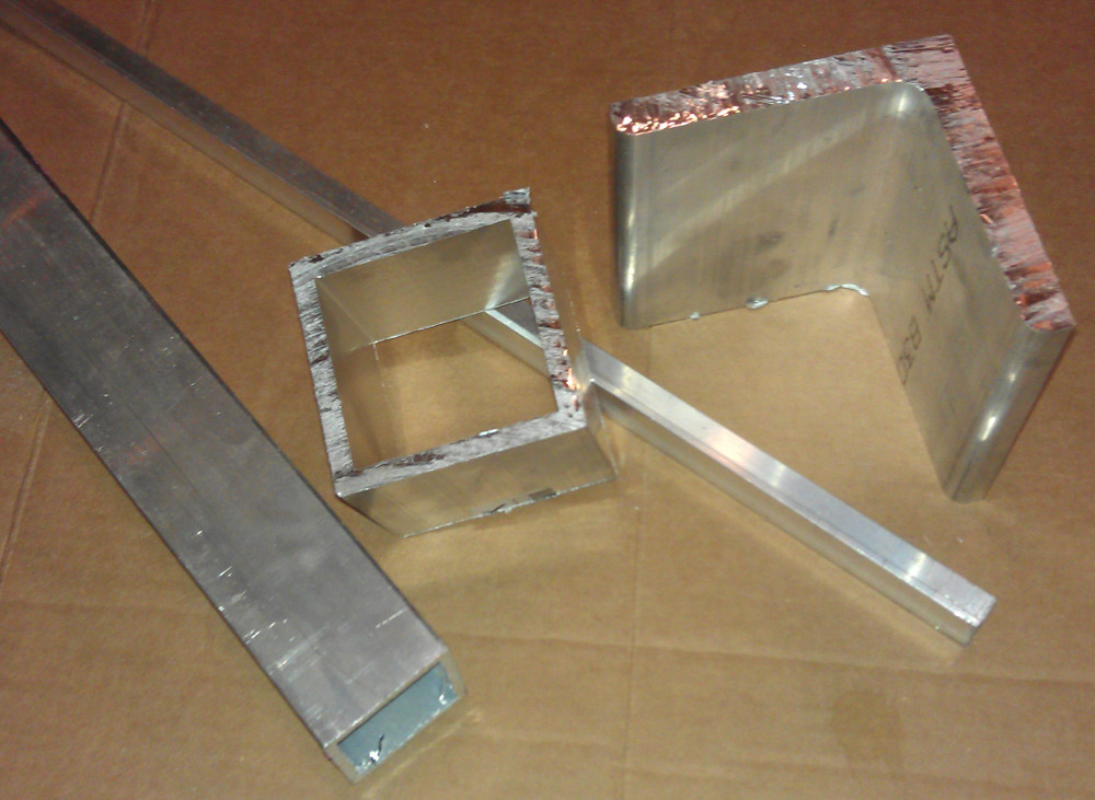
4” x 4”x 1/2” x 12” long Aluminum L angle
1/2” x 1/2” x 1/8” x 12” long Aluminum L angle
3” Square Aluminum tube with 1/4" wall thickness 12” long
1 3/4” Square tube 1/8” thickness walls 18” long
2- 3/4” x 1” compression spring I think McMaster-Carr #9657K314 will work but I bought mine at Lowes.
4- 1/2" X 1/4" Bushing with a 5/16” center hole
Spray paint can with the color of your Choice if you want it a pretty color…
Step 1:
Swapping out the crank to the opposite side of the jack so that a clockwise rotation compresses the bow. This is optional but make the operation a lot more intuitive.
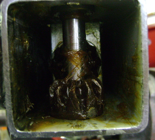
1) Remove the screw and grease fitting that hold the plastic end cap in place
2) Using a nail or a punch and a hammer pound the retaining pin out of the gear and crank. Extract the pin from the inside of the jack as it drops out.
3) Leave the gear in place and pull the crank out.
4) Drill a whole with the 9/16 drill bit about 5/8” from the end of the crank
5) Slide the crank back in on the opposite side of the jack and replace the press fit pin through the gear and into the new hole you just drilled.
6) Return the black end cap and grease fitting to the end of the jack.
Now when you crank the handle clockwise it will compress the jack.
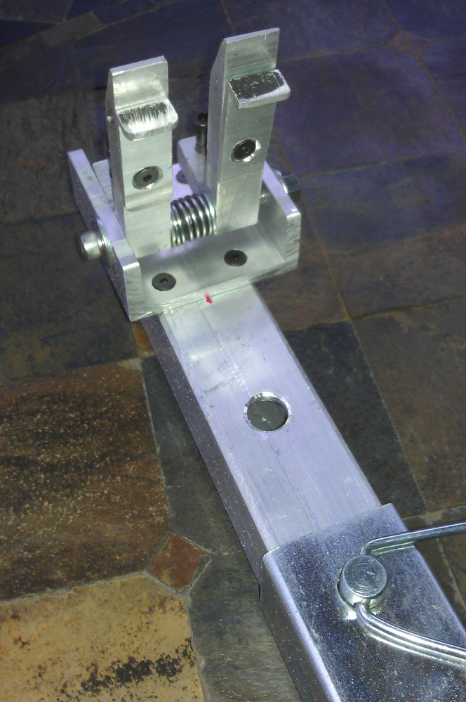
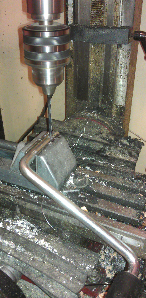
Step 2:
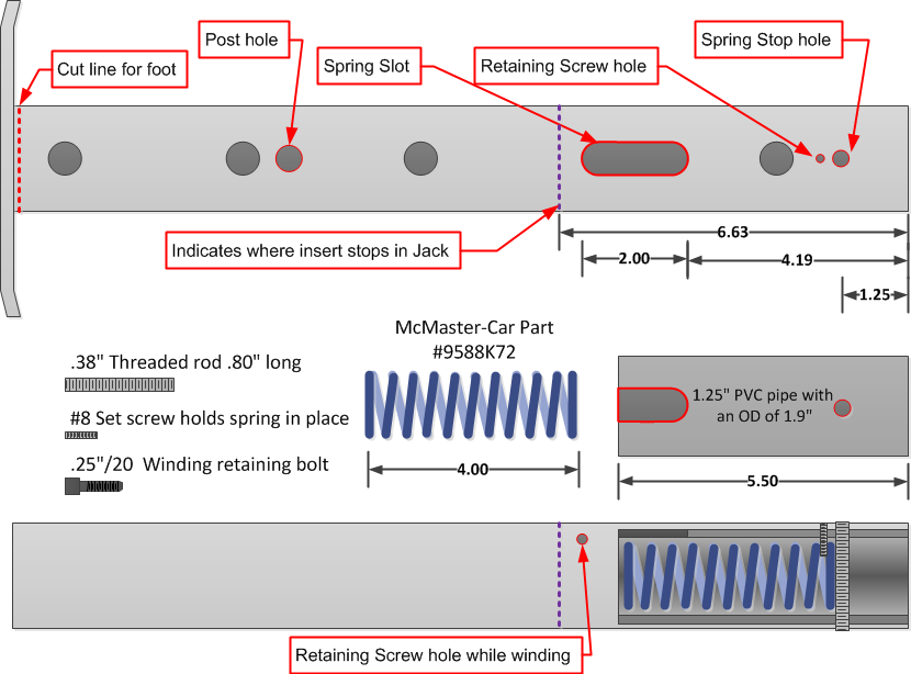
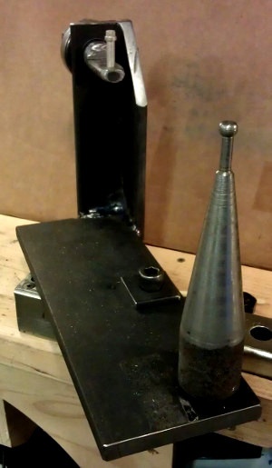
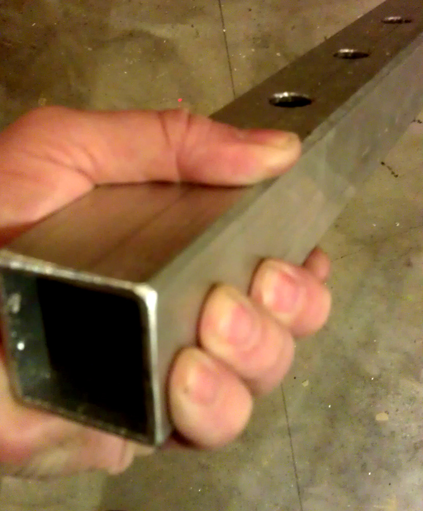
Creating the insert that fits into the end of the jack. You can use the foot that comes with the jack by cutting off the base but I found that it fits a little sloppy and isn’t really long enough to handle the longest bows. So I use the 1.75” Square Aluminum tubing.
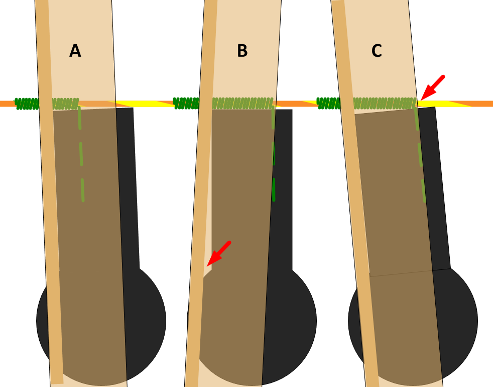
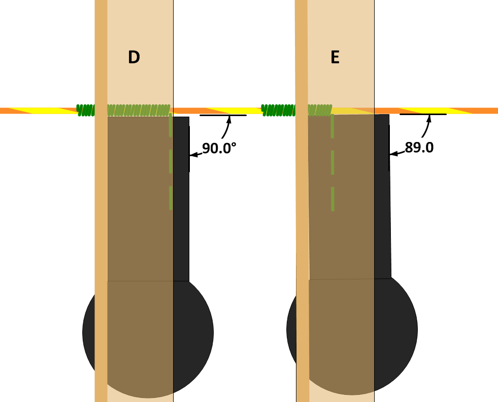
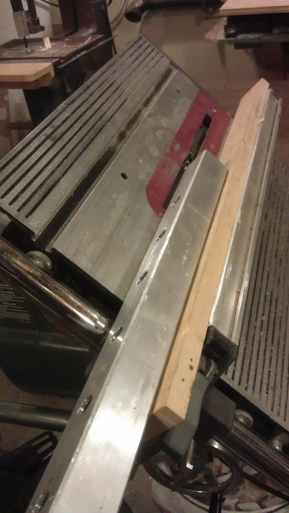
1) Set your table saw up at a 45 degree angle and chamfer each corner of the insert back about 1/8” This allows it to slide into the jack base.
2) If it fits real tight you may need to remove burs on the inside of the jack with a file.
3) Drill 4 holes 3” apart starting 4.5” on center from the end of the insert.
Step 3
Building the finger Assembly
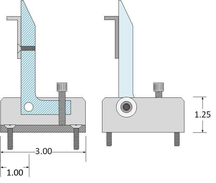

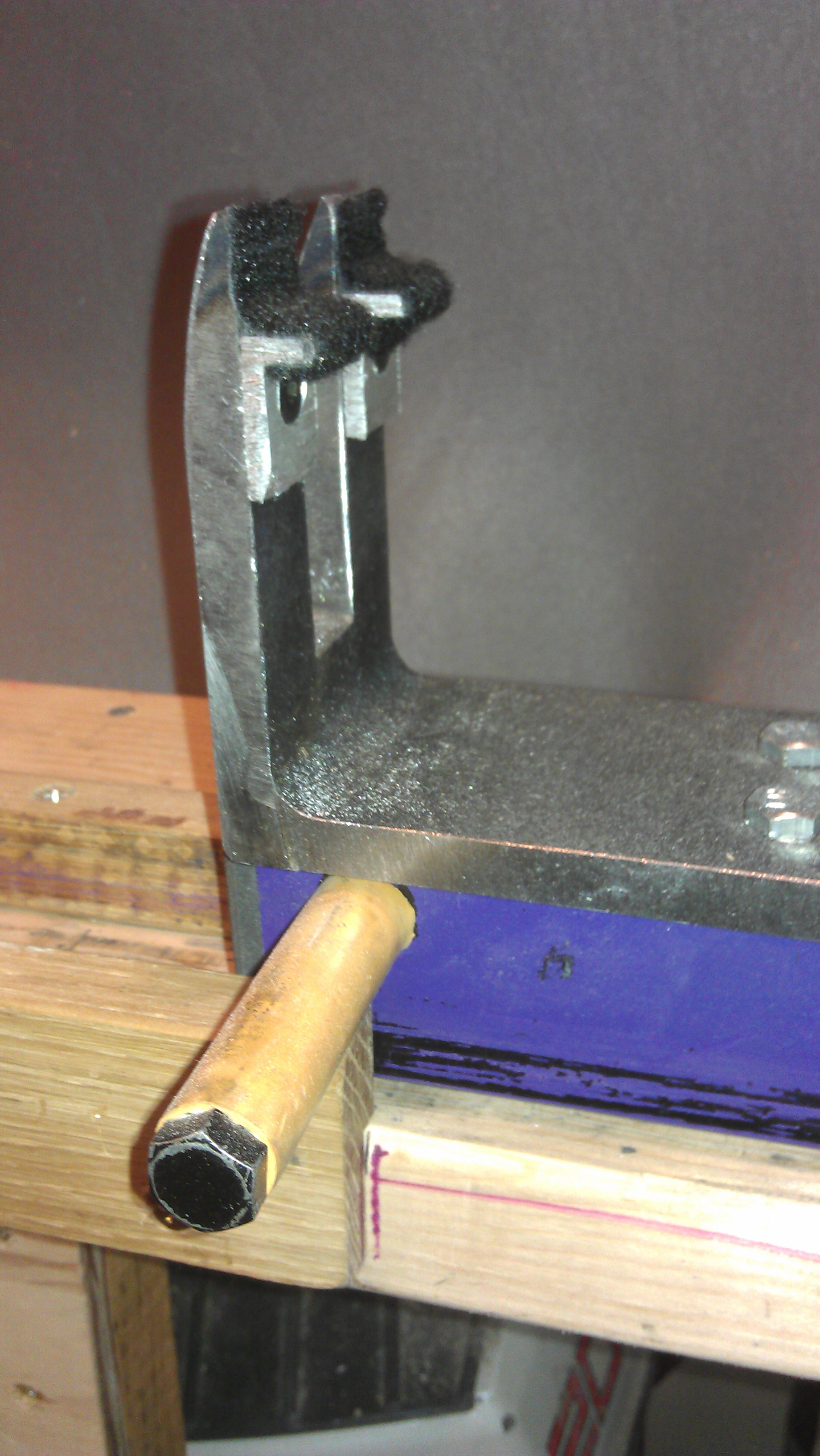
3.A Cutting and drilling the fingers.
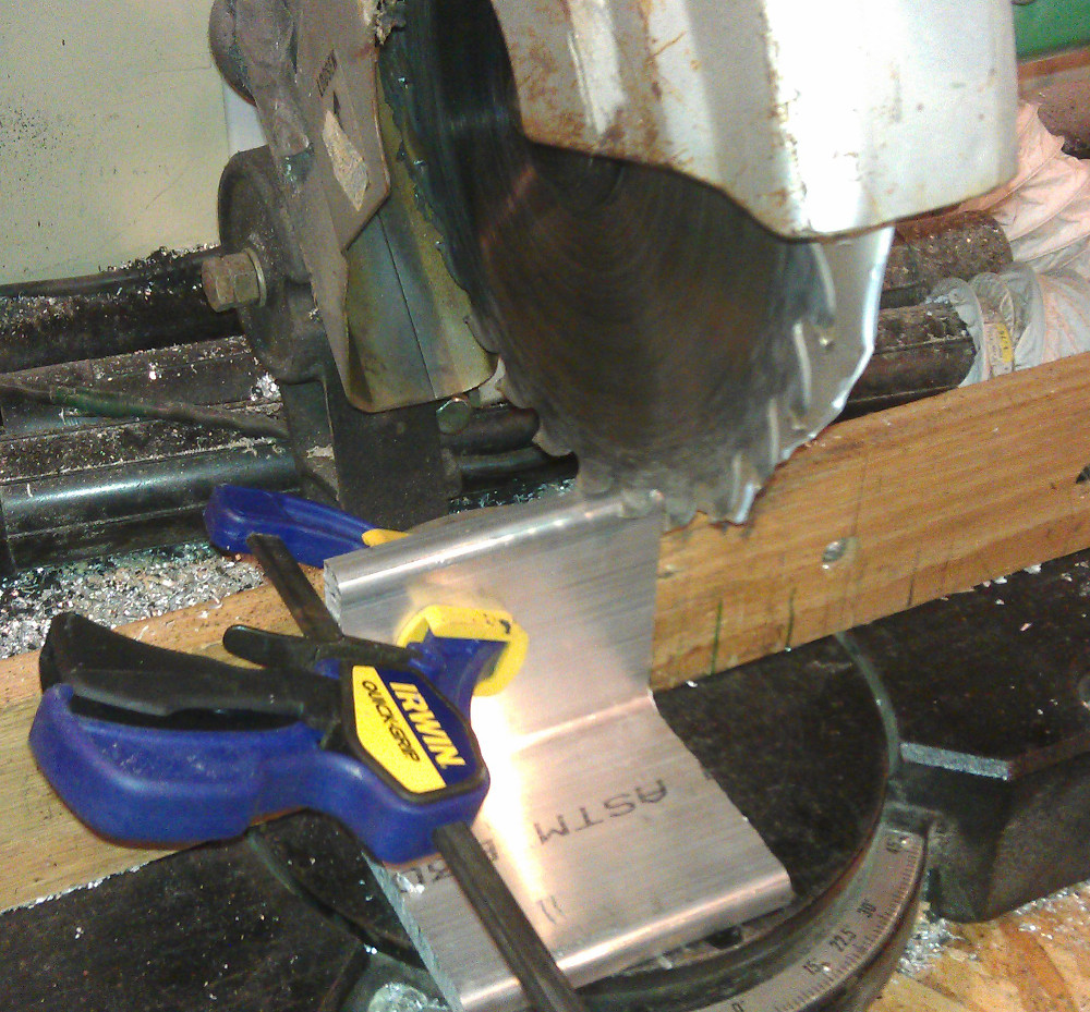
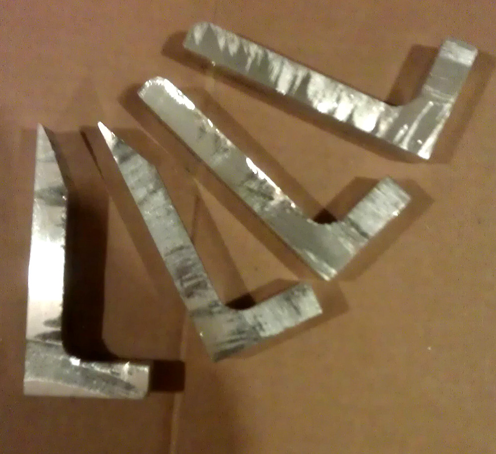
1) Using your chop saw cut the 4”x 1/2” Aluminum L angle in 4 pieces that are 3/4” wide. If you don’t like the rough finish cut them marginally wider so you can sand or mill the finish smooth.
2) Cut one side of the L angle to 1.75” long.
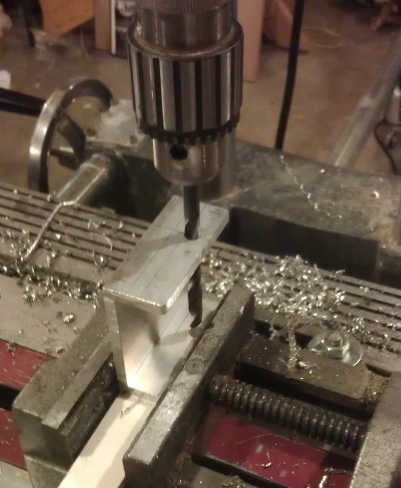
3) Setup your drill press with a clamp so you can drill all four finger with the F drill bit (the one for 5/16-18 tap) in the exact same place on each finger. By drilling all 4 exactly the same you ensure that the hole is consistently in the same place. Note when drilling metal you get a much cleaner hole and there is a lot less wear and tear on the equipment if you lubricate the bits and parts as you are drilling with cutting fluid or WD40 will also work.
4) Enlarge the hole on 2 of the fingers with the 5/16” drill bit
5) The two fingers that were not enlarged, using the 5/16-18 tap cut threads in the hole at the base of the fingers.
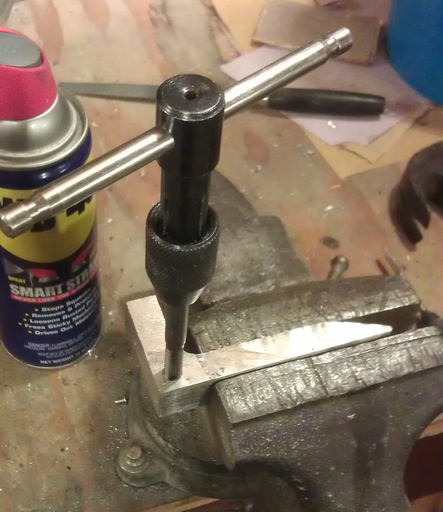
6) Again with a clamp on your drill press set so you can drill a consistent hole using the #24 drill bit (the one that came with the 1/4-20 tap) drill a hole in the foot of each finger centered 5/16” from the end
7) Using the 1/4-20 tap cut threads in each of these holes. Use plenty of cutting fluid or WD40 so avoid breaking the tap.
8) Using the number #7 drill bit drill a hole in the finger centered 1” from the top that you can use to bolt the limb shelf onto.
9) Using the 10/14 tap cut threads into the limb shelf hole.
10) Using the chop saw cut the 1/2” x 1/8” L angle to 3/4” wide pieces
11) Using the #9 drill, drill a hole in the center of one side of each of the limb shelf pieces.
12) Using the 10-24 screws bolt the limb shelf to the fingers.
13) Thread in the 4 -1/4-20 x 1” bolts into the fingers feet
Your fingers are now complete!
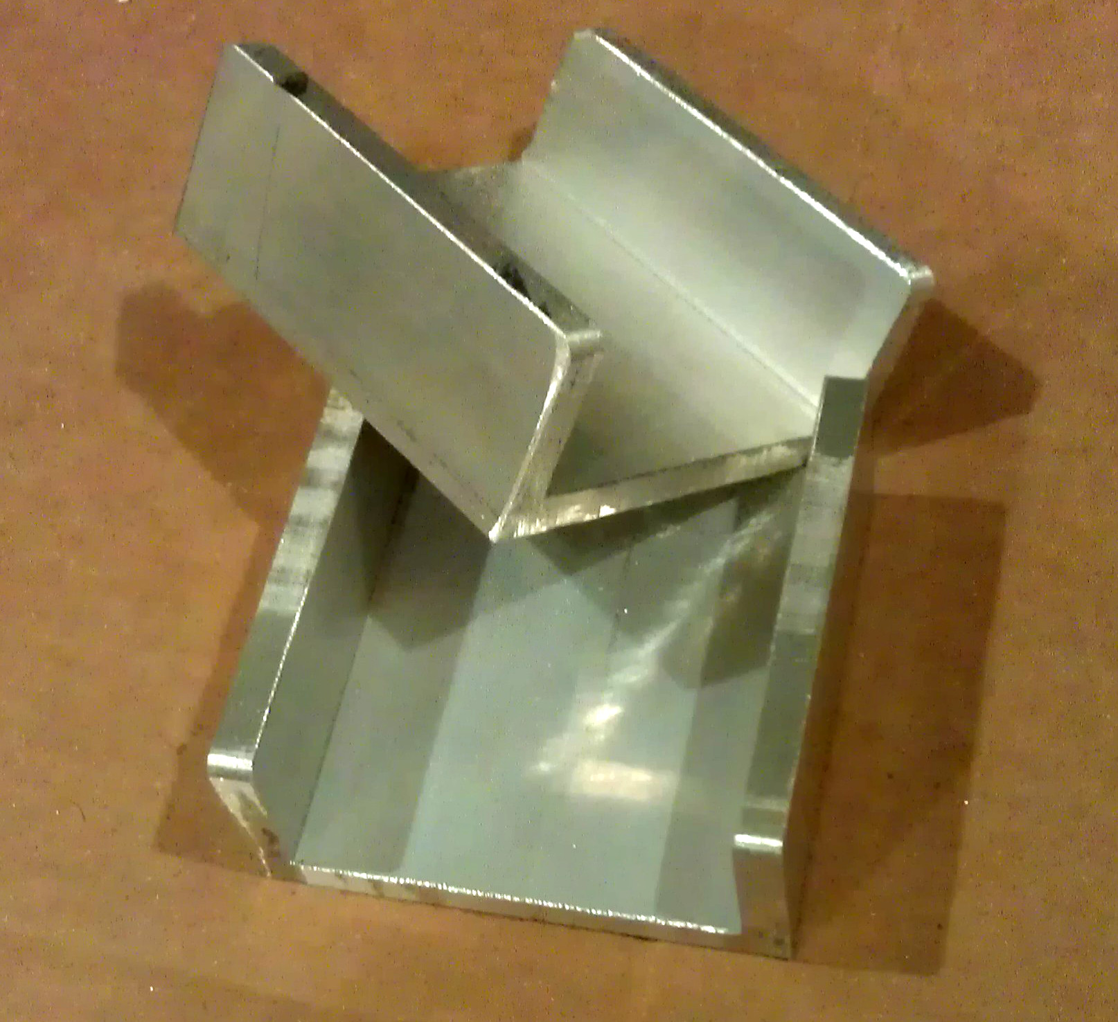
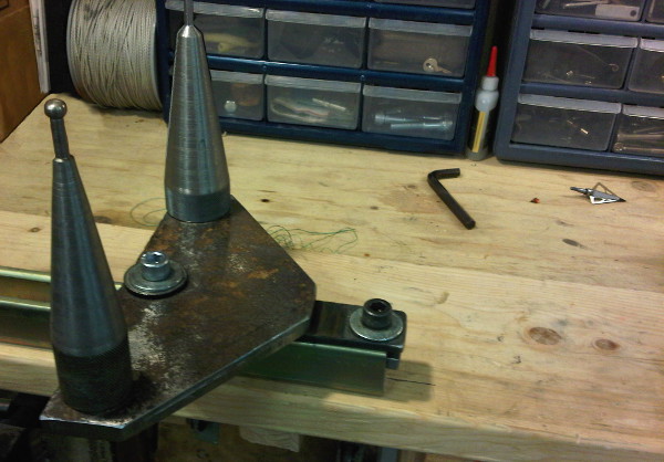
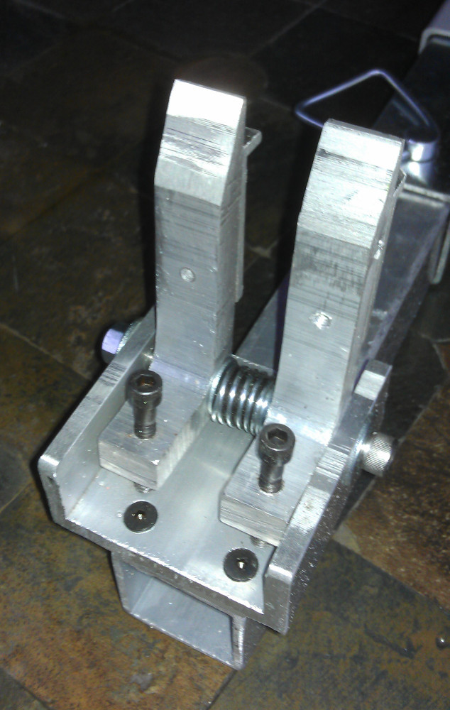
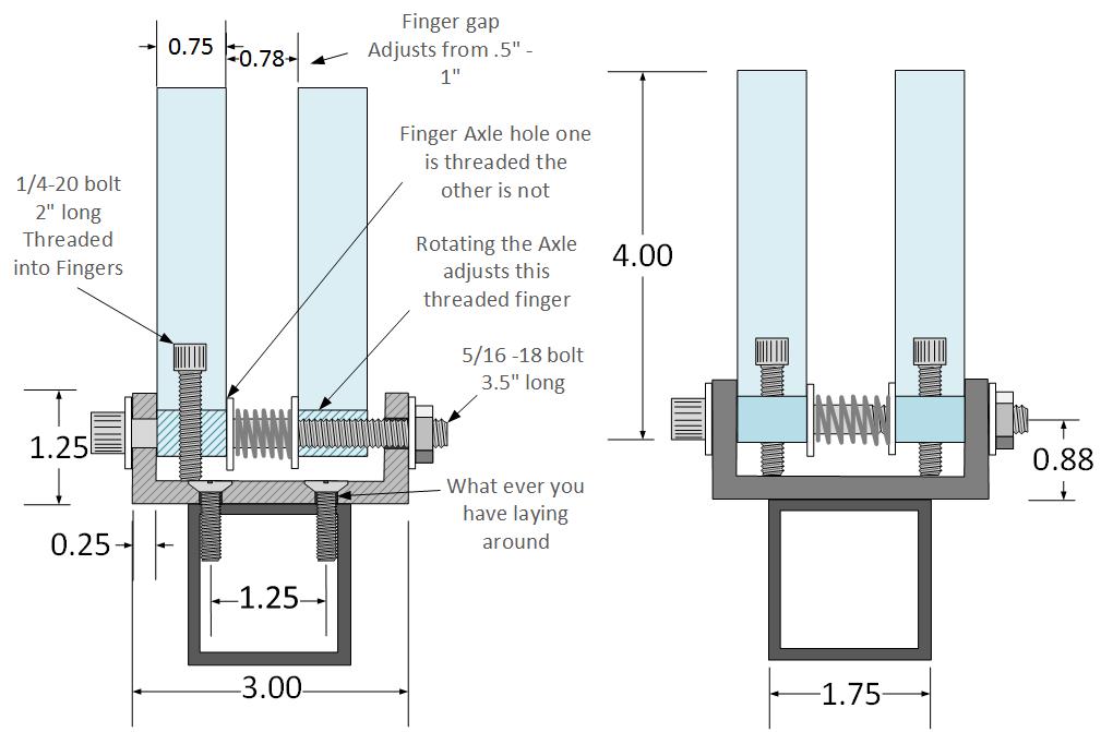
3.B Making the finger bases and assembling the fingers.
1) Using the chop saw cut a 3” long piece from the 3” square tube.
2) Now turn it sideways and with the shop saw cut the tube so that you have a U channel with 1.25” side wall. You’ll need to cut the other side so it too has a 1.25” side wall. You should now have 2 pieces that are 3”x3”x1.25”
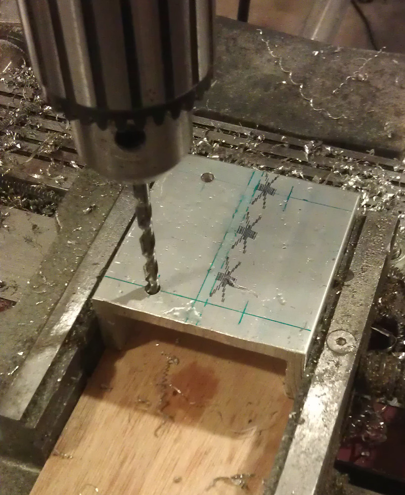
3) Using the 5/16 drill bit drill a hole in the 1.25” wall 2.125” from the end and 5/8” of an inch up from the bottom. This is the hole that the 5/16” bolts\shafts will got through to hold the fingers in place.
4) Using the 1/4” drill bit drill 4 holes in the base so that the finger base can be bolted to the insert and the Jack. Holes can be drilled 1/2" From the end and 1. 25” apart on center
5) Clamp the finger plates in place on the insert and on the jack frame and drill the mounting holes with the #24 Drill bit.
6) The 8 holes you just drilled now need to have threads cut with the 1/4-20 tap
7) Using the 1/4-20 bolts mount the finger bases to both the insert and the Jack.
8) Add a washer to the 5/15”x3.5” bolt and then lace it into the finger base now add the finger with the enlarged hole.
9) Add another washer and both plastic bushings
10) Slide the spring over the plastic bushings and then add another washer.
11) Compress the spring enough to slide the second threaded finger in-between the last washer and the outside finger base wall.
12) Rotate the finger shaft bolt to thread it into the second finger, thread it through until the bolt head is flush with the outside of the finger base. Now add a washer on the far outside of the finger base and thread on the shaft nut.
13) Make sure the finger shaft bolt rotates freely and then with a hammer mushroom the end of the bolt to prevent the nut from coming back off. A little epoxy wouldn’t hurt either.
14) Now by rotating the shaft bolt you can adjust the width of the fingers.
Step 4:
Cutting down the pin so that it fits in the jack when it is resting on the table.
Using a hack saw cut the adjuster pin to 2 7/16" long
Once you have done this to both ends of the press your press is now done!